
Panels
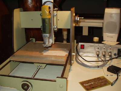
Offcourse you can buy them at FDS or AGT. I wanted to have more control over the design proces and design the panels around the hardware I had. I bought a CNC machine for this. Here you see the first results.
First I started with the design. I use CadStd-Lite. It is freeware, you can find it here
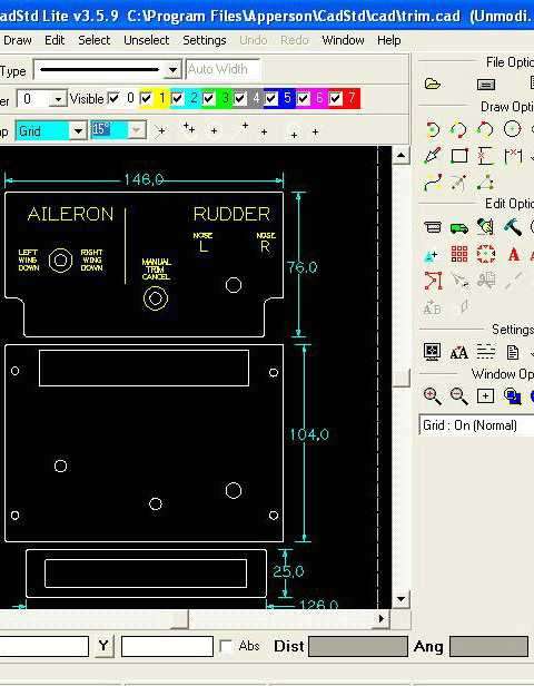
I started with the trim panel from the center pedestal.
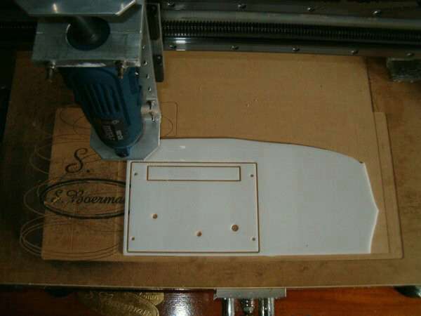
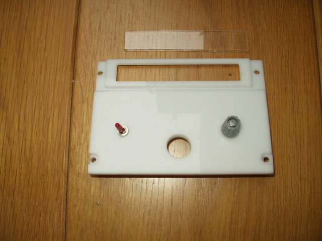
All panels in the centerpedestal will be made from 2 layers of white perspex. This gives a nice 3d look.
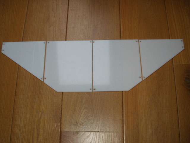
The beginning of the overhead. To save weight, I remove 1,5 mm around the "dzus" fasteners. This is a lot less work then making 2 layers and still looks quiet nice.
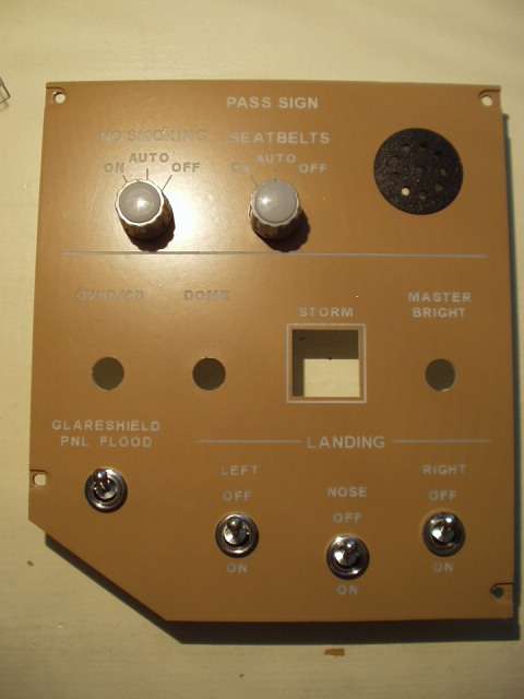
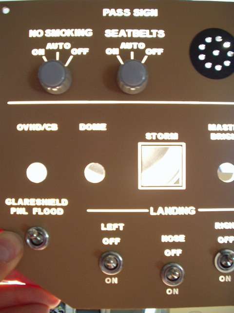
It is important to sand the panels wel and use special hardplastic primer. Otherwise some tiny parts of the engraved characters (like the A and B for example) will not hold to the plastic. Here is the first result. The pass sign panel in the overhead, with and without backlighting.
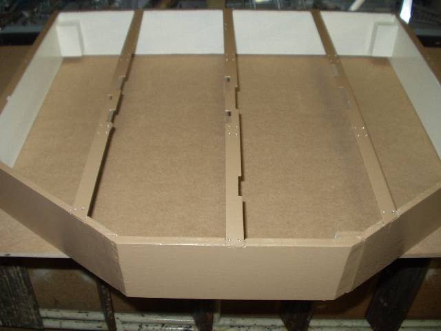
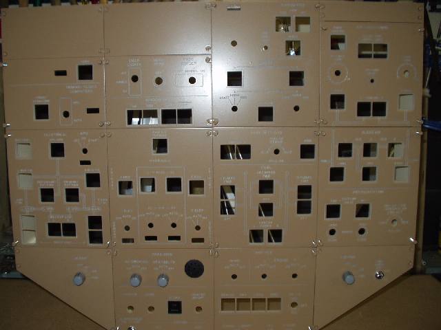
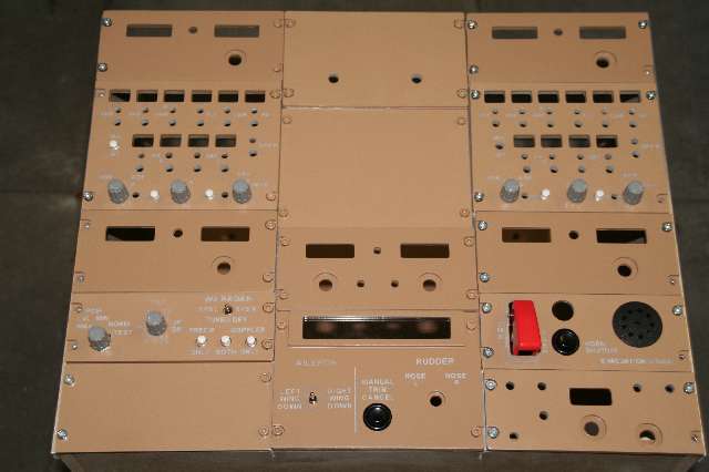
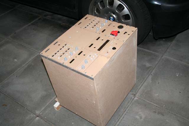
This is the box to which all the panels will be attached. The backplate is not there yet. The whole inside will be painted white, so it will better reflect all the light in the box.
All the panels connected.If you look good, you will see the first prototype korry already in place (storm light switch)
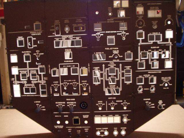
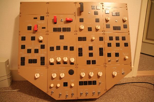
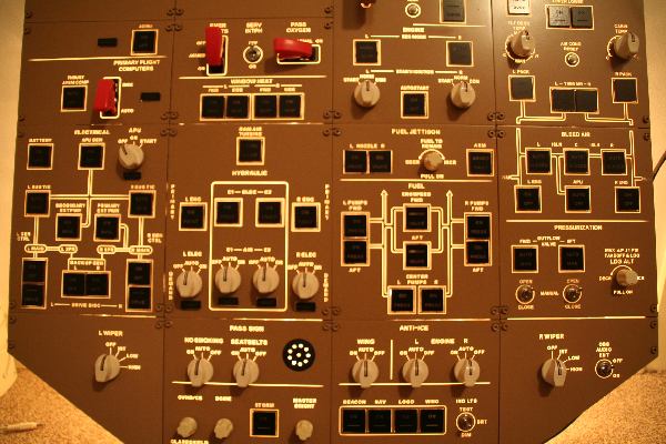
All the panels are cut, painted and engraved. In the pic is a normal lamp behind to give an impression of the backlighting. It will look much better when the real backlighting will be installed. Only about 65 korries to make !!.
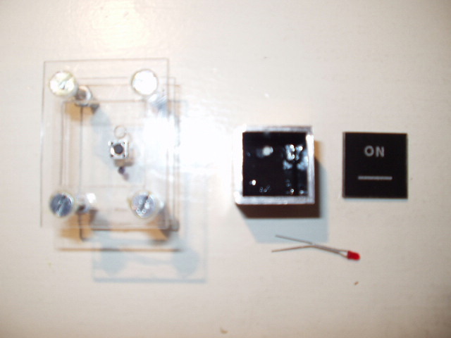
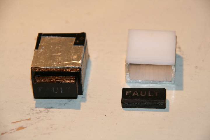
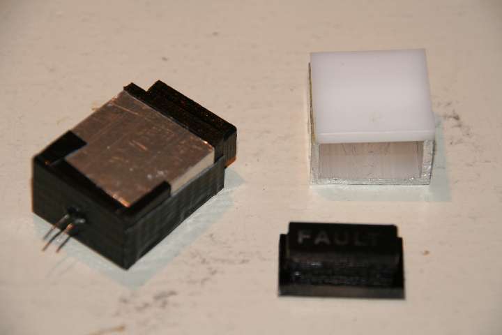
I started to make a prototype Korry switch for in the overhead. Here you see the CAD file of the design. I take a little microswitch. That is connected by a little plexi part and 2 spacers to the main panel. The main part of the body of the switch is made from aluminium (square profile 2 x 2 cm).
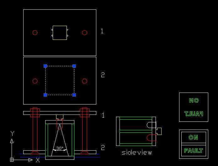
On the back of the alu body there is a plexi part that holds 2 Leds. The front part wil get a part of plexi painted black on the backside and engraved in mirror (ON, FAULT, ISLN etc).
On the Anti-Ice panel will be 4 korry next to each others (ext lights). I adjusted the basic CAD design a bit to hold 4 korry switches.
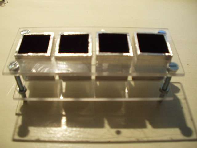
For the 8 annunciators I split a 25 x 25 mm square aluminium. The openings are covered with white plexi, the front with clear plexi.
The Led goes in the back, all is covered with tape to block the light.
Connected to FSLED, no tripod yet, sorry for the blur.

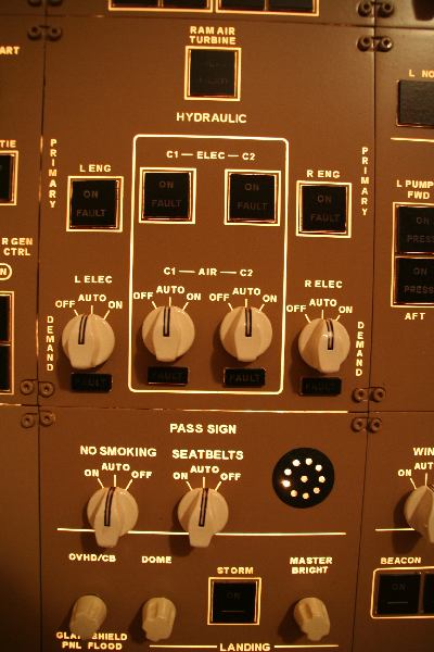
Detail ofthe hydraulics panel.
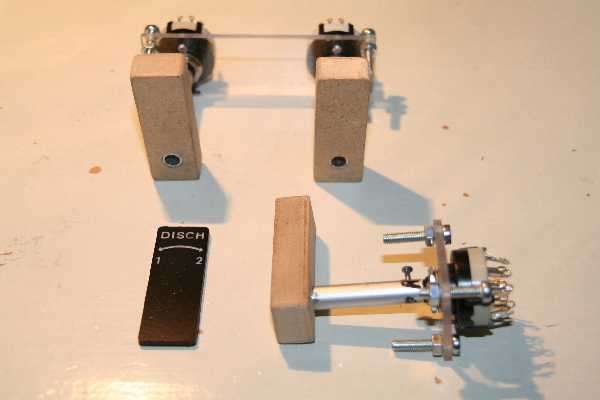
Here you see the fire bottle discharge switches. I just extended the rod of the 12 position switch. The switch is connected to a plexi backer that is connected to the back of the panel. In that way I will not see the nut of the switch.
The beginning af the rear part of the center pedestal. The throttle will follow soon.
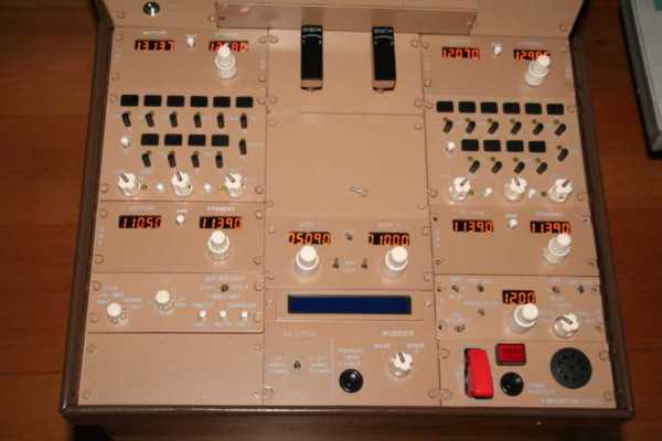
Completely lit. I had to use a pc powersupply to get it right. The AC/DC 5 V convertor I used gave only 0,8 Amp. That was not enough to lit al 54 7 segm leds. A standard PC powersupply is not working if it detects no load after starting up. Look here for info.
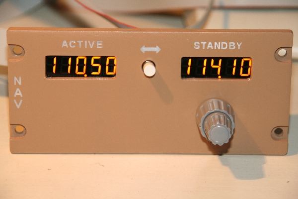
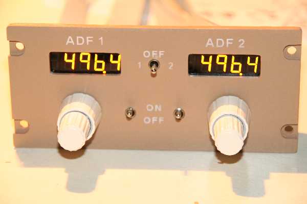
The NAV1 panel. FSBUS display is working fine.
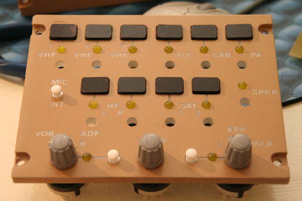
The RMP - radio managemant panel.
Trim panel. The LCD is driven by FSLCD. Unfortunately I can not get the last 8 characters to function. This panel gives me a visual feedback of the aileron and rudder trim, needed for 1 engine out procedures.

Completely lit. I had to use a pc powersupply to get it right. The AC/DC 5 V convertor I used gave only 0,8 Amp. That was not enough to lit al 54 7 segm leds.
A standard PC powersupply is not working if it detects no load after starting up. Look here or here for info.
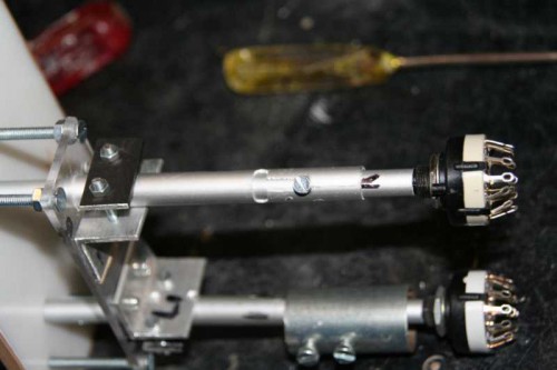
I rebuild the fire bottle discharge handle. Now I have to pull it before I can turn it. This is the inner part of the mechanism.
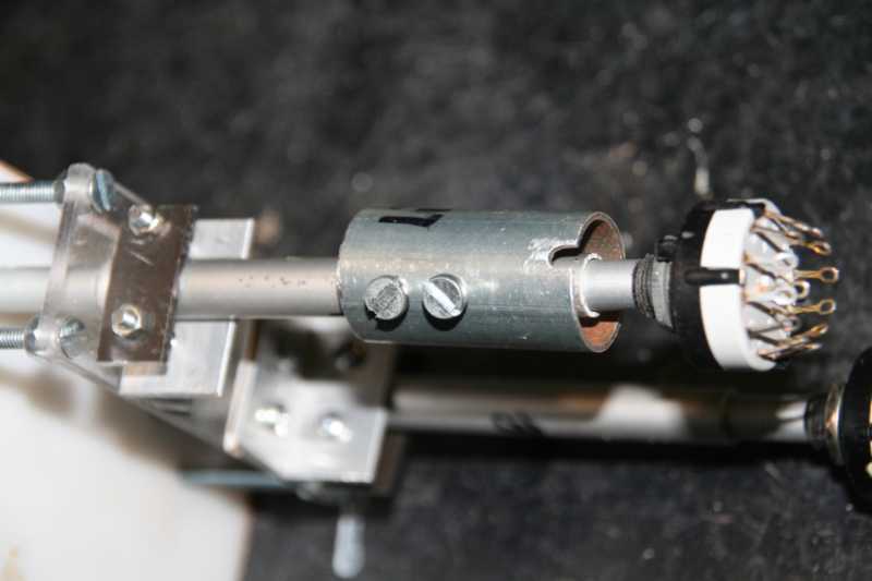
This is the outer part of the mechanism. The little black elevation of the 12 rotary switch comes in to the opening of the outer ring to prevent the switch from turning. I also made a light in the handle.
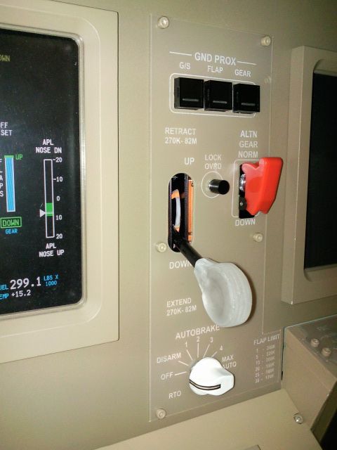
The gearpanel is complete. The gear knob is the first 3D CNC object I made.
For engraving I made a floating Z axis. When you start engraving, you'll notice that the routerbit will remove not the same amount of paint on all parts of your panel. The paint or the bottom on which the panel is lying is not 100% flat.
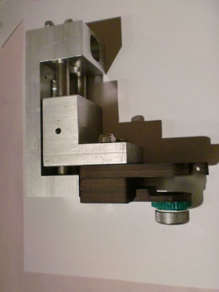
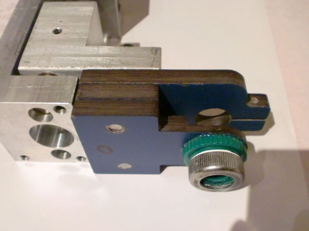
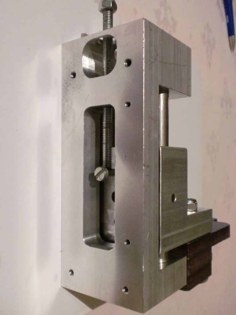
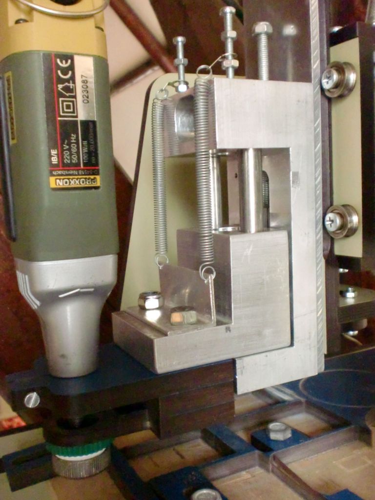
When I turn the lower alu ring it allows the end of the router bit to remove the paint. In the CAM software I enter as depth -0,5. In fact that is far to much but when the alu ring touches the surface of the panel, the floating part of the z axis is lifted.Two little springs remove a part of the weight of the floating z axis. It is important that the lower alu ring does not damage the surface of the panel. In the past I had to engrave word by word. That was very timeconsuming. Now I will be able to engrave the whole panel in one time. Too bad that most engraving work is done. But it was fun to make this thing.